
A laptop Screen Connector with labelled Pins 1-40
No Backlight or DIM or Dark Screen, Blank Screen or Black Screen on Laptop.
In the ever-evolving landscape of LCD technology, the ability to troubleshoot power issues is paramount for ensuring optimal display performance. When faced with a non-responsive screen, the culprit often lies in disruptions to the power supply to the LCD backlight. In this comprehensive guide, penned by an LCD expert, we will delve into the nuances of testing power outputs from your screen cable using a multimeter, focusing on EDP and LVDS screens. Additionally, we will emphasize the critical importance of caution during these tests to prevent potential damage to your backlight fuse, which may necessitate a surface mount replacement.
Introduction: Navigating the LCD Power Maze
Before we embark on the journey of testing LCD screen power, it's essential to understand the integral role of the screen cable in delivering power to the LCD backlight. EDP (Embedded DisplayPort) and LVDS (Low Voltage Differential Signalling) screens are prevalent in modern displays, with their cables acting as conduits for both power and data transmission. When your screen refuses to power on, the issue may stem from a disruption in the power supply to the LCD backlight.
The Tools of the Trade: Multimeter Basics
Arming yourself with the right tools is the first step in troubleshooting LCD screen power issues. A multimeter, a versatile instrument capable of measuring voltage, current, and resistance, becomes an indispensable ally in this diagnostic journey. Before commencing testing, ensure your multimeter is set to measure DC voltage.
Identifying Power and Ground Pins: Deciphering the Connector
To effectively test for power, one must first identify the power and ground pins on the screen cable connector. While the specifics can vary based on the screen and connector type, a general guide is provided below:
Identifying Power and Ground Pins on EDP Connectors:
Embedded DisplayPort (EDP) Overview:
EDP is a high-performance interface utilized in many modern displays. When testing for power on an EDP connector, look for pins that supply the necessary voltage to the LCD backlight.
Power and Ground Pins on EDP Connectors:
- VDD (Voltage Drain): This pin often carries the power supply for the screen and backlight. Confirm the voltage in the technical documentation, commonly around 3.3V.
- GND (Ground): The ground pin serves as the reference point for the electrical circuit.
- BL_PWR: These indicate that there are multiple pins that power different sections of the screen's backlight. You'll need to test all of them.
Identifying Pins:
Reference the technical documentation for your specific display to identify the exact pins for VDD (power) and GND (ground). Power pins may be labelled as VDD, VCC, or have other designations indicating a positive voltage supply.
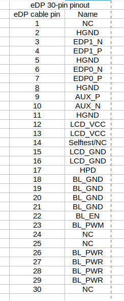
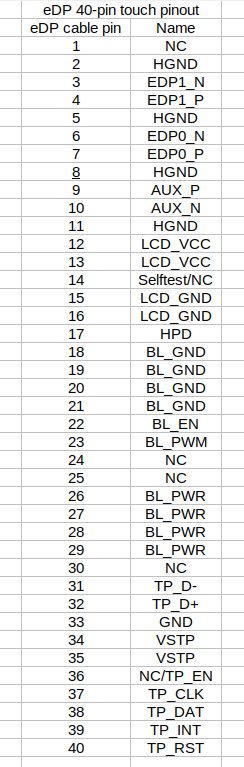
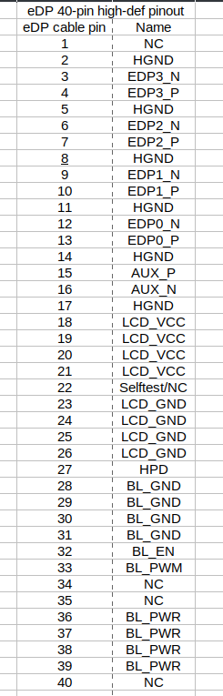
Example EDP connector Pinouts
30 PIN Connector EDP (2 Lanes)
40 PIN Connector EDP 2 Lanes + Touch Screen
40 PIN connector EDP 4 Lanes (QHD/UHD resolution)
BL_PWR
In some cases, especially for larger displays or displays with multiple backlight zones, there may be more than one pin designated for backlight power. Each "BL_PWR" pin may be associated with a specific section of the backlight, allowing for finer control and adjustment of brightness levels.
When dealing with multiple "BL_PWR" pins, it's crucial to consult the technical documentation provided by the display manufacturer or the device specifications to understand the specific configuration and requirements. The documentation should provide details on the voltage levels, current ratings, and any other relevant information for each "BL_PWR" pin.
Here's a general breakdown of the "BL_PWR" pins:
BL_PWR1, BL_PWR2, etc.: Multiple pins may be used to power different sections or zones of the backlight. Each pin is associated with a specific part of the backlight for finer control.
Voltage Levels: Confirm the voltage levels for each "BL_PWR" pin. It's not uncommon for backlight power to be around 3.3V, but this can vary based on the display specifications.
Current Requirements: Take note of the current requirements for each "BL_PWR" pin. This information is crucial for ensuring that the power supply can provide sufficient current for the backlight.
Always refer to the specific documentation provided by the display manufacturer or the device specifications to ensure accurate and safe connections. Incorrectly connecting power pins can lead to damage to the display or other components. If in doubt, consult with the manufacturer's technical support or seek assistance from a qualified professional.
Identifying Power and Ground Pins on LVDS Connectors:
Low Voltage Differential Signaling (LVDS) Overview:
LVDS is another common interface used in LCD displays. When testing for power, focus on the pins responsible for supplying voltage to the backlight.
Power and Ground Pins on LVDS Connectors:
- VCC or VDD (Voltage Supply): Similar to EDP, LVDS connectors typically have a pin responsible for providing power to the display. Confirm the voltage in the technical documentation, usually around 3.3V.
- GND (Ground): Locate the ground pin to establish the electrical reference point for the circuit.
Identifying Pins:
Consult the technical documentation for your display to identify the pins specifically designated for power and ground. Look for pins labelled VCC, VDD, or other indicators denoting a positive voltage supply.
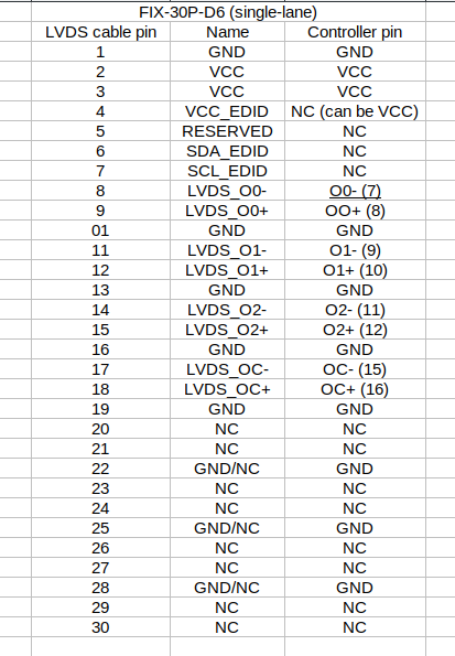
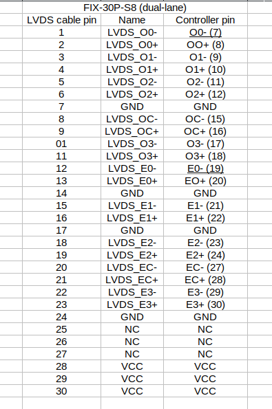
Common LVDS Pinouts
FI-X 30-pin connector single-lane 6-bit pinout
FI-X 30-pin connector dual-lane 6-bit pinout

FI-X 30-pin connector dual-lane 8-bit pinout
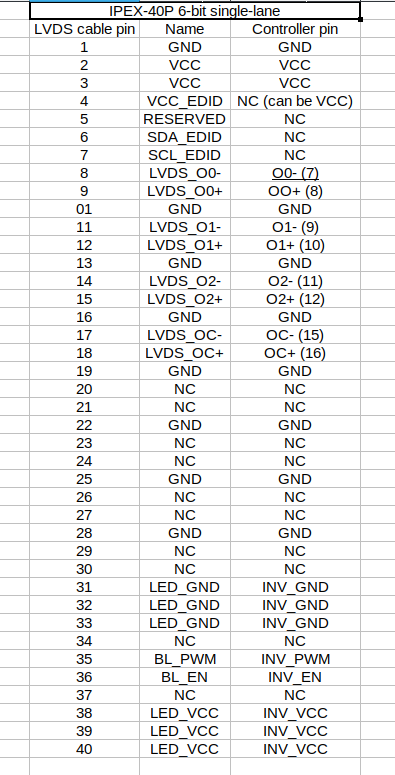
IPEX 40-pin connector single-lane LED 6-bit pinout
IPEX 40-pin connector dual-lane LED 6-bit pinout

Testing Power Using a Multimeter:
Setting Up the Multimeter:
Set your multimeter to measure DC voltage in the appropriate voltage range (e.g., 0-5V or 0-10V, depending on the expected voltage for your display).
Probe Placement:
Carefully insert the multimeter probes into the identified power (VDD or VCC) and ground (GND) pins on the connector.
Interpreting Readings:
Power on the device and observe the multimeter readings. If the voltage is within the expected range, the power supply to the LCD backlight is likely functioning correctly.
Cautionary Measures:
- Avoid shorting any connectors during this process to prevent damage to the backlight fuse on the motherboard.
Conclusion: Navigating the LCD Troubleshooting Landscape
In conclusion, the ability to test for power outputs from your screen cable is an invaluable skill for LCD users grappling with non-responsive displays. Armed with a multimeter and a precise understanding of connector anatomy, you can efficiently diagnose power issues. However, exercise caution to avoid short circuits, preventing damage to the backlight fuse on the motherboard. By following this guide with precision and care, you empower yourself to unravel the mysteries of LCD power troubleshooting, ensuring your display continues to illuminate the digital landscapes of your daily life.
